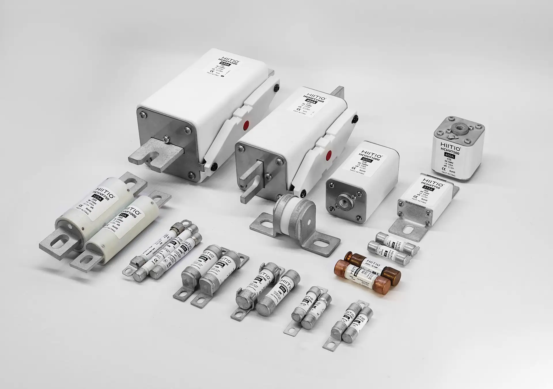
With the widespread application of semiconductor fuses across various industries and the increasing complexity of working environments, the process of selecting fuses requires comprehensive consideration of multiple key factors. This article aims to delve into several common selection parameters of fuses to assist readers in better understanding and application.
System Operating Voltage(V):
The system operating voltage refers to the voltage range endured by all devices and components within a circuit, including the fuse itself. Selecting the correct system operating voltage is a crucial factor in ensuring that the fuse operates properly, protecting the circuit and equipment from overload and short-circuit damage.
Rated Voltage(Vac/Vdc):
The rated voltage of a fuse refers to the highest operating voltage of the circuit in which the fuse is installed while it is in a safe operating state, i.e., the voltage range within which the fuse can sustain safe operation. This indicates that the rated voltage of the fuse must be equal to or greater than its system operating voltage; otherwise, continuous arcing and voltage breakdown may occur during fuse operation, jeopardizing the integrity of the circuit.
Rated Current(A):
The fusible element (link) of a fuse is specially designed to withstand a specified amount of current continuously without opening the circuit. This is known as the rated current of the fuse. In other words, the rated current of a fuse refers to the maximum current value at which the fuse can safely operate.
When the current in the circuit exceeds the rated current of the fuse, the fuse will actuate based on specific mechanisms designed into its construction, interrupting the circuit to protect equipment and circuits from damage due to overload or short-circuit conditions.
Therefore, when selecting a fuse, it is essential to ensure that its rated current matches the rated operating current of the circuit to ensure effective protection under both normal and abnormal operating conditions.
Current Limiting Characteristics:
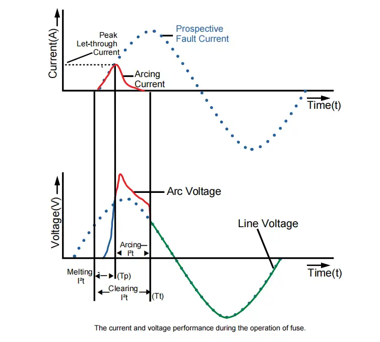
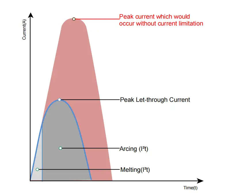
The thermal energy generated during the interruption of fault current in a fuse is typically expressed in joules, commonly referred to as Ampere-squared seconds (A²s or I²t). It is directly proportional to the square of the current (‘I’ in amperes) within the operating time (‘t’ in seconds). The generated thermal energy is represented by melting I²t, arcing I²t, and clearing I²t.
Melting I²t:
This is the thermal energy passing through the fuse from the occurrence of over-current to the melting of the fuse element. It is equal to the square of the root mean square current multiplied by the melting time (unit: seconds).
Arcing I²t:
This is the thermal energy passing through the fuse during the arc discharge period. It is equal to the square of the root mean square arc discharge current multiplied by the arc discharge time (unit: seconds).
Clearing I²t:
Also known as total fuse I²t, this is the I²t passing through the fuse device from the occurrence of over-current until the current is completely interrupted. (Clearing I²t = Melting I²t + Arcing I²t)
Time-Current Curve:
The time-current curve of a fuse represents the relationship between the time of operation and the current load at different current levels. This curve is typically plotted on logarithmic coordinates, with the horizontal axis representing the logarithmic value of the current and the vertical axis representing the logarithmic value of time. On the curve, as the current increases, the operation time may decrease sharply, reflecting the characteristic of the fuse acting faster at higher currents.
How to determine the fuse melting time?
To determine the melting time of a fuse, first, identify the fault current. Then, locate the position of the fault current on the X-axis (point A). Next, extend vertically from point A until it intersects with the Time-Current curve of the fuse’s rated current (point B). Finally, shift point B horizontally to the corresponding position on the Y-axis (point C), which represents the arc-preceding (melting) time of the fuse.
Taking HCHVT500-250UD-38R as an example, suppose the applied fault current is 1600A. Mark the position of point A on the X-axis and extend it upward until it intersects with the TC curve at 250A, determining point B. Finally, mark the position on the Y-axis corresponding to point B (point C = 0.2s). Therefore, for HCHVT500-250UD-38R, the arc-preceding (melting) time at 1600A is 0.2s.
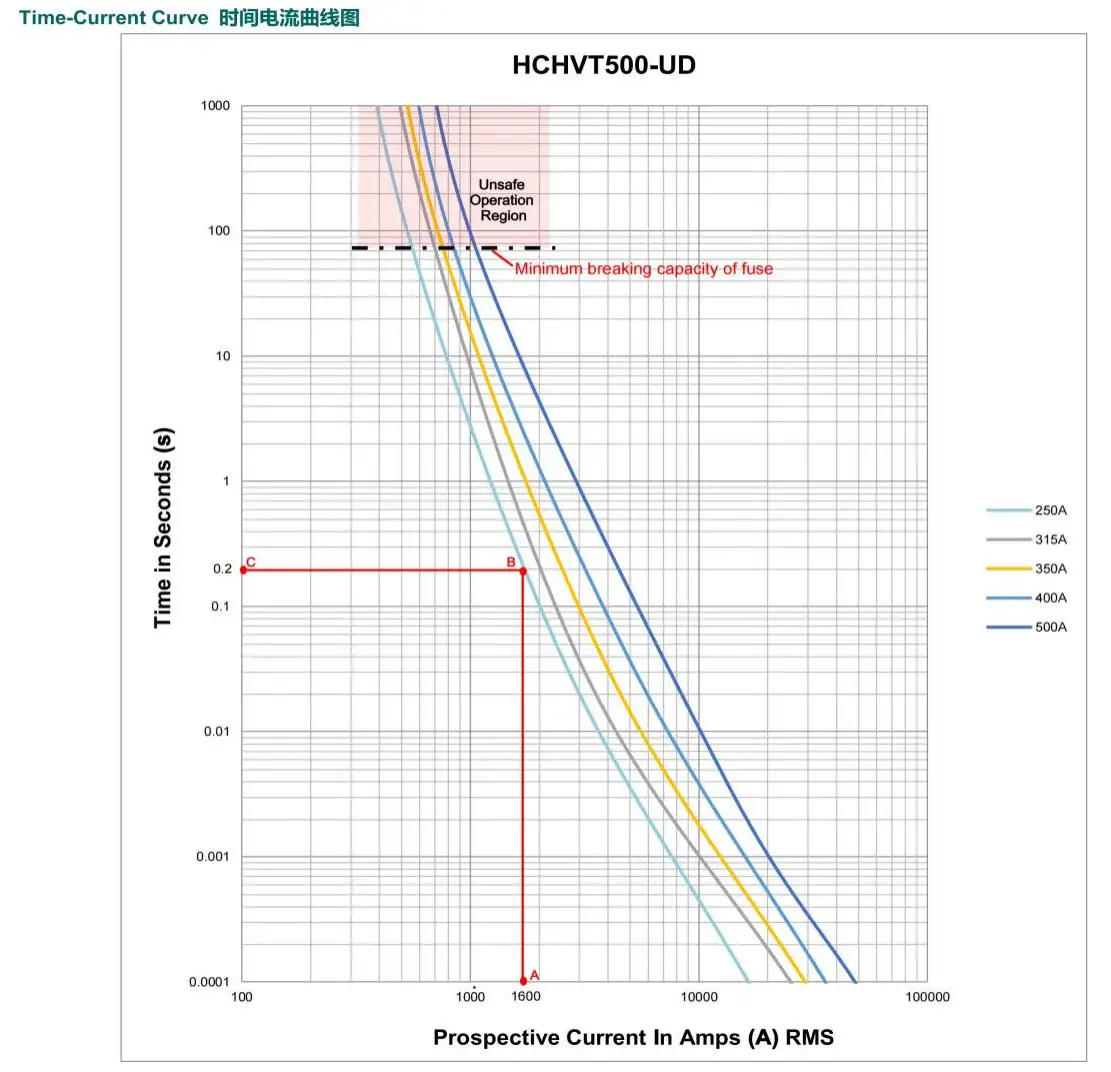
Note: The current range outside the fuse’s protection limits (typically small overload fault currents) is represented by dashed lines. The intersection of solid and dashed lines indicates the minimum breaking current of the fuse. Due to the significant thermal risk associated with using high-speed fuses in the case of small over-currents, it is not recommended to operate within this area (shaded region marked).
Operating Environment Temperature:
Since the operation of a fuse is directly influenced by heat, the ambient temperature directly affects the performance of the fuse.
In addition to the indoor or outdoor temperature around electronic and electrical equipment, the ambient temperature here primarily refers to the temperature of the fuse in the small environment inside the machine. If the fuse is installed on a closed fuse holder, then the ambient temperature is the temperature of the air immediately surrounding the fuse holder. It decreases as the ambient temperature rises, and vice versa.
How to determine the Temperature Derating factor?
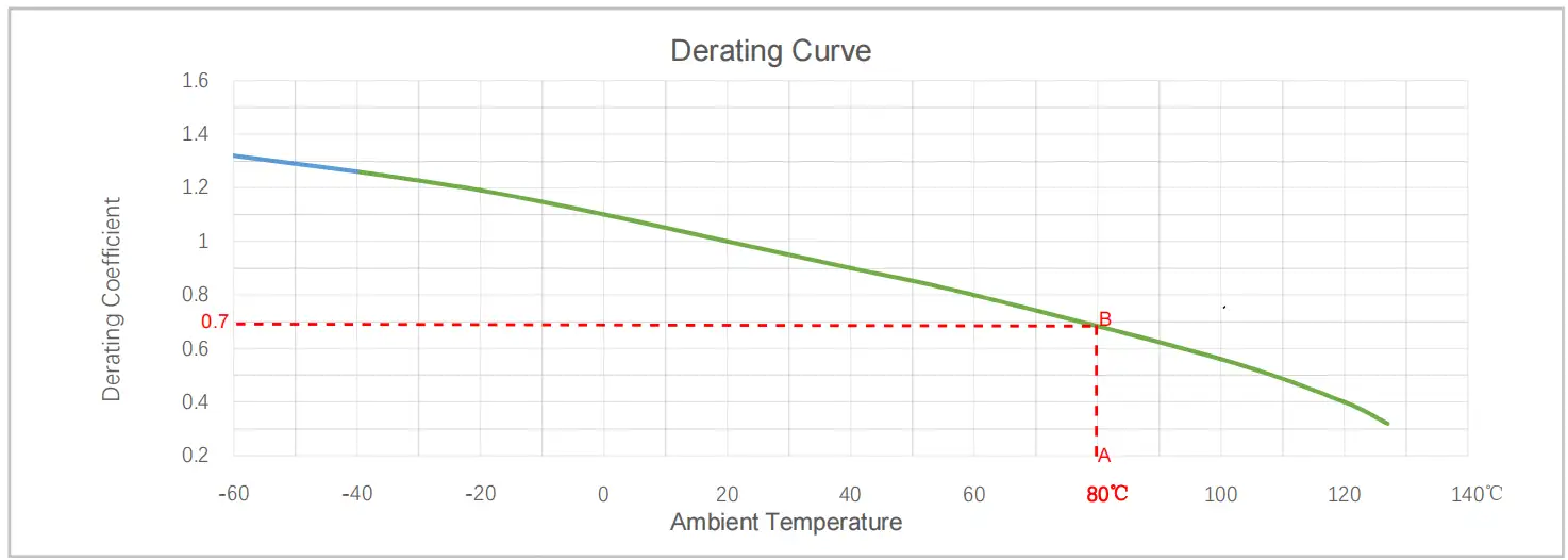
The temperature derating curve illustrates the variation in the current-carrying capacity within the operating temperature range of the fuse. It shows the safe operating temperature range (X-axis), also known as the operating temperature range, for the fuse, as well as the corresponding derating coefficient to be applied to the rated current of the fuse.
To determine the corresponding derating coefficient of the fuse, first measure the ambient temperature of the application environment and locate its position on the X-axis. Then, extend a line upward from this reference point until it intersects with the derating curve. Next, move horizontally to find the corresponding percentage displayed on the Y-axis.
Taking HCHVT250-250UD-38R as an example, suppose the ambient temperature for this application is 80℃. Locate the corresponding point A on the X-axis, then extend upward until it intersects with the derating curve (point B). Move horizontally to find the corresponding value on the Y-axis, which is “0.7”. Thus, under this operating condition, the derating coefficient of the selected fuse is 70%. This means that the rated current of the fuse should be increased by 70%: 250A + 70% = 425A. Therefore, the recommended rated current for the fuse is 450A.
Peak Current(A):
The peak current of a fuse refers to the instantaneous maximum current value occurring in a circuit. In a circuit, peak current may arise due to transient faults, overcurrent events, or other sudden occurrences. This current may be several times or even tens of times greater than the normal operating current in the circuit.
Fuses are typically designed to operate under specific current loads and to melt when their rated current is reached to prevent overload in the circuit. However, if there is a transient high peak current exceeding the rated value of the fuse, the fuse may immediately actuate to protect the circuit, preventing damage or fire hazards.
Therefore, the peak current of a fuse refers to the maximum current value that the fuse can briefly withstand. It is commonly used to evaluate its performance and applicability range.
Peak Current Duration(s):
The peak current duration refers to the length of time during which the peak current occurs in a circuit. This period is typically brief, measured in milliseconds or a few seconds. The duration of the peak current depends on factors such as the type of fault occurring in the circuit, power supply characteristics, load conditions, and the response speed of the fuse
Time Constant (ms):
When fuses are used in DC circuits, it’s crucial to consider the complex effects of inductance and capacitance energy. Therefore, the time constant(L/R) is an important parameter that cannot be ignored. It is typically expressed in milliseconds (ms). The time constant determines the arc-extinguishing energy, breaking time, and permissible voltage. The larger the time constant T of the system circuit, the higher the energy transferred to the arc during breaking, making it more difficult for the fuse to interrupt. Therefore, the selection of fuse body thickness and length must be reasonable and safe.
Application Scenarios:
Power fuses are primarily used to protect high-energy circuits and find applications in various sectors including power generation equipment, energy storage devices, various transmission cables, high-voltage circuits in new energy vehicles, electric charging stations, photovoltaic systems, high-power inverters, and various industrial power supplies.
Fuse Selection:
If you are interested in understanding how to choose the appropriate fuse in-depth, we suggest you refer to our previously published related articles. Additionally, you can also fill out the form in the attachment (mandatory fields are marked with asterisks) and submit it to our team. We will assign professional personnel to match the most suitable product for you based on the requirements you provide.

