In the realm of electrical engineering and power system design, overcurrent protection is an essential element for maintaining safety, reliability, and performance. Among the many protective devices available, fuses continue to hold a vital role due to their simplicity, reliability, and rapid response to fault conditions.
This blog provides a comprehensive and in-depth look into the fundamentals of fuses—covering their working principles, technical terminology, types, standards, and advanced selection considerations—equipping you with the knowledge needed to make informed protection system decisions.
Definition
Under specified voltage conditions, current passes through the melt. When heat is accumulated to a certain extent using the thermal effect of the current, a special part (narrow diameter) of the melt melts and disconnects within a specified time, thereby safely interrupting the fault current device.

Use and purpose
- Protect the circuit to prevent circuit damage and fire.
- Protect the equipment to prevent fire or explosion if the equipment is damaged.
- Isolate faults to prevent accidents from expanding and limit faults to as small a range as possible
Explore more insights in our related post:
What Are High Rupturing Capacity (HRC) Fuses
They safeguard equipment and users by interrupting excessive currents before damage occurs. A fuse typically consists of a thin metal element enclosed in a case. Under normal operation, it conducts current without change, but when the current rises above its rated current, the element heats up and melts, breaking the circuit and stopping current flow. Because of this clear “weak link” behavior, fuses are inexpensive to replace yet highly reliable.
A blown fuse


Fundamentally, fuse responds to overcurrents (excess currents) caused by faults or overloads. When the current exceeds the design threshold, the fuse element heats quickly to its melting point, creating an open circuit. Fuses act faster under short-circuit conditions than under moderate overloads. In a high short-circuit, the intense current causes the element to melt in just milliseconds (often well under half an AC cycle), which limits the peak of the fault current.
The function of “sand” in the fuse

Note: When the fuse blows, the sand acts as an arc extinguisher. It will absorb the energy of the instantaneous arc, metal melting, and other energy, and “wrap” it to form “lava”. Insulate the line from the load. Eliminate the risk of arc breakdown and splash burst.
Recommended read:
The Working Principle of a Semiconductor DC Fuse
Material Properties and Manufacturing Process of High Voltage Fuses
In this current-limiting mode, the fuse actually reduces the magnitude and duration of the fault current, thereby protecting upstream equipment from damage. A key part of the interruption is the fuse’s filler material (usually fine quartz sand) around the element. When the element melts and an arc forms, the sand absorbs the arc’s energy and quenches it almost instantly by forming a high-resistance “lava” layer.
Overload current protection process


DC must extinguish the arc by the arc voltage and internal impedance of the fuse. Without a zero crossing point, the difficulty of extinguishing the arc increases significantly.
Fuses behave differently on AC versus DC systems due to the waveform. In an AC circuit, the current naturally crosses zero each half-cycle, helping to extinguish the arc every cycle. In contrast, a DC circuit has no zero crossings, so once a DC arc forms, it can sustain unless interrupted by the fuse’s voltage and internal resistance.
For this reason, DC-rated fuses often have larger element gaps and specially designed fillers to aid arc extinction. In either case, once the fuse element melts, the circuit is opened very rapidly, protecting the rest of the system. In summary, a fuse “works” by the simple heating effect of current: a thin wire melts when overheated, opening the circuit and safely stopping current flow.
Key Technical Terms and Ratings
Several specialized terms describe how fuses are specified and compared. Before that, we need to make it clear that HRC or High Rupturing Capacity Fuses are special types of fuses designed to protect electrical circuits from high currents, especially during events like short circuits or power surges.
Most important is the rated current (Iₙ), which is the maximum continuous current the fuse can carry indefinitely without degrading. The fuse is also marked with a rated voltage – the maximum system voltage at which it can interrupt current safely. Always choose a fuse whose voltage rating is at least as high as the circuit’s voltage so the fuse can withstand the system voltage during interruption.
The interrupting rating or breaking capacity of a fuse is another critical specification. This is defined as the largest fault current (at the rated voltage) that the fuse can safely clear. In practice, many industrial fuses have interrupting ratings from tens of kiloamperes (20–100 kA) up to 250 kA or more. A properly chosen fuse must have a breaking capacity equal to or greater than the maximum short-circuit current that could occur in its circuit.


A useful way to compare and coordinate fuses is via their time-current characteristic curves. A time-current curve plots the fuse’s melting time (or clearing time) against different levels of overcurrent. It shows, for example, that at 200% of rated current the fuse may take a certain number of seconds to blow, while at 1000% it blows in milliseconds.
Accurate time current characteristic curve, inter-stage selectivity with protection function:
- Fuse: Under certain working conditions, different overcurrent values and different action times have precise one-to-one correspondence. The interstage fuses in series connect to each other through matching parameters to protect the action. The order can be selected precisely.
- Circuit breaker: The action time has transition and cut-off characteristics in a certain area, the accuracy is low, and the short-circuit breaking time has a cut-off line of action time. The selection of inter-stage protection cooperation cannot be reliably realized. Selective.
Time current curve of a freely decaying short-circuit current

These curves are typically supplied in data sheets and indicate both the ability to carry 100% rated current continuously and the guaranteed blowing time at overload points (often 135%–300% of rating). Engineers use these curves to coordinate fuses (selectivity) by ensuring a downstream fuse blows faster than an upstream one at a given fault current. Time-current curves also let designers check that short surges (like motor starts) do not prematurely blow the fuse.
Another key parameter is I²t (the melting integral or thermal energy). I²t is the integral of the square of the current over time during the fuse’s melting process. In other words, it measures how much energy is absorbed by the fuse element up to the moment it opens. The higher the I²t, the more energy the fuse lets through before interrupting. Fuses usually have two I²t values: pre-arcing I²t (energy up to the onset of arcing) and total clearing I²t (energy until arc extinguishes).

For protection coordination, designers often compare a fuse’s I²t with the I²t withstand rating of sensitive components (e.g. semiconductor devices or cables). A fuse chosen to protect a device should have a clearing I²t lower than the device’s withstand I²t, ensuring the fuse blows before the device is damaged. In DC circuits, the I²t of a given fuse can differ from AC tests (typically it may be higher or lower depending on circuit characteristics).

Note: The higher the fault level (the greater the energy density of the short circuit, when designing, consider the direction of the smaller cutoff peak value and faster time. 1. Shorter troubleshooting time. 2. Decrease the let-through current to a smaller level.
Another outstanding performance: current limiting characteristics, expected short-circuit current wave without connecting the fuse
- The fault current generated by the electrical parameters of the fault circuit without connecting the fuse is called the expected (fault) current. AC is marked with an effective value.
- AC circuit breakers generally use zero-point arc extinguishing, and the switch has the ability to break higher amplitude currents.
- In case of DC high current faults, circuit breakers, contactors, relays, and other switches are difficult to break, mainly because the switch structure has difficulty in arc extinguishing.
- The life of switch-type electrical appliances breaking large-value overcurrents is also limited. Except for ACB (frame circuit breakers have several lives), the limit current value breaking is regarded as a one-time device.


Fuse access circuit: The actual current of the circuit through which a short-circuit high-current fault passes is significantly less than the expected current (dashed line), which is called the current-limiting characteristic.
- The short-circuit current amplitude is limited, and the duration is greatly reduced.
- Then the allowed fault energy (I²t-Joule integral value) is greatly reduced compared to the switch breaking, which can be as small as one percent or even less than one ten thousandth.


Other common terms include:
- Cut-off current (Iₚ) – the peak instantaneous current let through by a fuse during a fault (the peak let-through current). In current-limiting mode, a fuse “clips” the fault current well below the available bolted fault. A lower Iₚ means better limiting. Manufacturers often provide peak let-through charts or tables so designers can see, for each prospective fault, the maximum RMS and peak currents that would flow.
- Pre-arcing time – the interval from the start of fault current until the fuse element completely melts (but before the arc extinguishes).
- Clearing time – the total time from fault inception to current fully interrupted. Clearing time includes a brief arcing interval after melting.
Related Content:
Semiconductor Fuse Core Parameter Guide
These metrics (time-current curves, Iₚ, I²t, etc.) are all interrelated. For example, two fuses might have the same Iₚ but different clearing times, resulting in different I²t values. In general, a faster fuse (shorter clearing time) will have lower I²t and provide better protection for downstream components. Thus designers use I²t and let-through data to ensure proper fuse selection and coordination.
Fuse Classification
By Function
Fuses are classified by the type of protection they provide. The international standard IEC 60269 (and its national variants) uses a two-letter utilization category code. The first letter is “g” or “a”:
- g (Full-range fuse) – a general-purpose fuse that protects against both overloads and short-circuits. For example, a gG fuse is “general” use, meaning it will clear any current from about 1.3×Iₙ up to its maximum interrupting capacity. Most line and conductor protection fuses are gG type.
- a (Back-up fuse) – a short-circuit only fuse (also called partial-range). An “a” fuse does not blow at moderate overloads; it only operates on high fault currents. These are typically used in series with other protection devices. For instance, aR (or aR) fuses are designed solely to protect sensitive semiconductors in case of severe short-circuits (they let small surges pass). Similarly, aM fuses are backup protection for motors (acting only on high faults, not normal starts).
| Type | Application | Scope of Protection |
|---|---|---|
| aM | Short circuit protection for power circuits | Partial protection (auxiliary) |
| aR | Semiconductor protection large breaking protection | |
| gG | Universal type: mainly conductor protection rated current to maximum breaking protection | Full protection |
| gM | Power circuit protection | |
| gN | North American general type: conductor protection | |
| gD | North American universal delay type | |
| gR,gS | Semiconductor protection | |
| gTr | Transformer protection | |
| gL, gF, gl,gll | The former fuse type has been replaced by the gG type | Full protection |
Please note: 1.”Full range” can break any overload current that is enough to cause the fuse to melt (generally from 1.3 times rated to the maximum breaking capacity). Full range fuses are available for individual protection devices (conductors, lines mainly). 2.”Partial range” or “backup” fuses are designed to interrupt short-circuit currents only. The breaking capacity is higher than that of other subsequent components and protection devices.
The second letter indicates the application or range. Common letters include G (general), M (motor circuits), R (semiconductor devices), and N (specific general duty, e.g. US/Canada). For example, gG (full-range general) is for general conductor protection (replacing older terms like gL/gI), gM is a fast fuse for motor starters, gR is a full-range semiconductor fuse, and aR is a backup semiconductor fuse. In North America, UL uses different terminology (Class J, T, CC fuses, etc.), but designers often translate UL classes to approximate IEC categories when coordinating systems.
In practice, a g-type (general) fuse placed in a circuit will interrupt both typical overloads and short circuits. An a-type (backup) fuse will not respond to moderate overloads; it only serves as a safety in the event that a lower-level device fails. For example, an aR fuse is chosen to handle only catastrophic short circuits on a bus, whereas routine motor overloads are handled by relays or breakers.
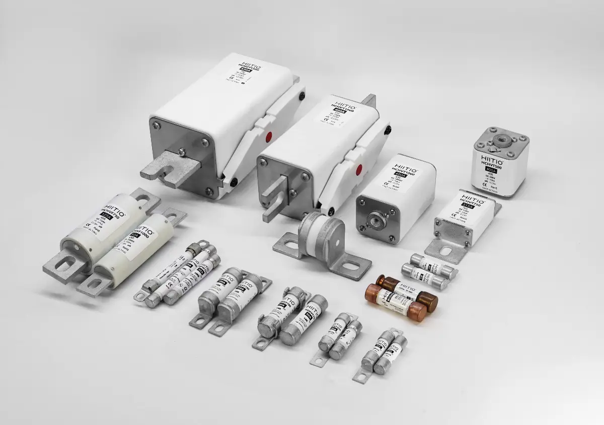
By Physical Style
Fuses also come in many physical forms or mounting styles. Common categories include:
- Cartridge (cylindrical) fuses: These fuses have a cylindrical body (often ceramic or glass) with metal end caps. The interior contains the fusible link and sand filler. Cartridge fuses range from small glass tubular fuses (e.g. in electronics) to large industrial DIN-rail or NH fuses. High-Rupturing-Capacity (HRC) fuses – a term often used synonymously with “gG” – are typically cartridge style with rugged ceramic bodies.
- Bolt-on (bolted tag) fuses: These have flat metal tabs or lugs on the ends that are bolted into fuse holders. Bolt fuses (sometimes called bolted-tag fuses) are used for high-current circuits and in switchgear. The fuse link itself may still be cylindrical inside the holder; the bolt-on style simplifies installation in high-current panels. Example: large bus fuses or battery fuses.
- Blade (plug-in) fuses: Widely used in automotive and low-voltage applications, blade fuses have one or two flat blade terminals that plug into a socket. They are often small plastic-bodied fuses (mini, ATO, MAXI, etc.) rated up to a few tens of amps at 12–32 V. Blade fuses make it easy to replace blown fuses without tools.
- Knife-switch fuses and strip fuses: Older or specialty designs use a knife or lever that physically presses on a fuse link. For example, panel-switch units may have a built-in fuse blade.
- Cuboid (rectangular block) fuses: These fuses feature a compact, box-like shape and are commonly used in high-power applications such as EVs, battery packs, and renewable energy systems. They typically offer high interrupting capacity and are designed for bolt-down or busbar integration. Cuboid fuses combine robust thermal and mechanical performance in a dense form factor, making them ideal for systems with space and safety constraints.


Beyond shape, fuses are also distinguished by design features such as cartridge body material or speed rating. For instance, HRC fuse (High Rupturing Capacity) generally means the fuse has high interrupting ability and typically contains arc-quenching material. The technical definition is simply “high breaking capacity” (capable of safely interrupting very large currents).
Typical Representative Size


Related Post:
The Difference Between Semiconductor Fuse and HRC Fuse
Pyro Fuses vs. Traditional Semiconductor Fuses: A Comprehensive Comparison
How to Choose A Suitable Class RK5 Fuse?
How to choose a Semiconductor DC Fuse?
In summary, a procurement manager will encounter fuse types named by both code and style: e.g. “10A gG cylindrical fuse, 500VAC” or “30A aM bolt-in fuse” or “15A automotive blade fuse”. The function (g/a category) tells you what protection it provides, and the style (cylindrical, blade, bolt, etc.) tells you how it is mounted.
Typical Application Scenarios
Fuses are widely deployed across diverse sectors to ensure electrical safety, protect critical equipment, and maintain system stability. Key application scenarios include:
- Industrial Power Electronics: Used in variable frequency drives, rectifiers, and automation systems to protect components like IGBTs and MOSFETs from overcurrent damage, ensuring reliable factory operations.
- Electric Vehicles (EVs): Safeguard high-voltage circuits such as Battery Disconnect Units (BDUs), onboard chargers, and fast-charging ports, playing a vital role in EV safety and performance.
- Renewable Energy Systems: In solar inverters, wind turbines, and energy storage units, semiconductor fuses provide fast fault isolation, especially critical in preventing thermal runaway and fires in large-scale ESS applications.
- Data Centers & UPS: Protect rectifiers and inverters in uninterruptible power supply systems, preventing costly downtimes and preserving critical digital infrastructure.
- Rail Transit: Ensure safe and stable operation of traction inverters and onboard electronics in high-speed rail and urban metro systems, supporting both passenger safety and system reliability.
Each scenario requires precise fuse selection to match voltage, current, response characteristics, and form factor.
Expand Your Knowledge:
Exploring the Applications of Semiconductor Fuses
Application of DC Fuses in Energy Storage Systems
Application of Semiconductor DC Fuse in EV DC Charging Station
The Critical Role of Pyro Fuses in Energy Storage Systems
Core Advantages of Fuses
Fuses offer several intrinsic advantages that make them attractive for circuit protection:
- High interrupting capacity: Modern fuses can clear very large fault currents quickly. Low-voltage fuses commonly interrupt 20–100 kA; some designs reach 200–250 kA. This high breaking capacity is achieved at relatively low cost. Fuses can safely clear near-gross-faults (close to source) without external quenching equipment. Their ability to clear a short-circuit in a tiny fraction of a cycle (well under half-cycle in current-limiting operation) means much of the fault energy is never realized. This current-limiting action significantly reduces the thermal and mechanical stresses in the system. In fact, by isolating the fault before the current peaks, fuses limit the total energy delivered to the fault. Less energy means lower risk of fires or explosions and less damage to switchgear. As one arc-flash study notes: a current-limiting fuse might predict only ~0.3 cal/cm² incident energy in a fault, versus 9+ cal/cm² if the fault cleared in six cycles.

- Fast response (strong limit): Because fuses rely on thermal melting, they respond extremely fast to high currents. Under a severe fault, a fuse can melt in milliseconds, limiting current to a fraction of its asymptotic peak. This fast operation helps protect sensitive loads (like power electronics) and improves system safety. The I²t (energy let-through) of a fuse is generally very low compared to slower devices, meaning less heating of conductors and connected equipment during a fault.
Representative fuse I²t diagram

Note: At maximum fault power when flowing, the molten tube’s Forearc Joule integral and fuse joule product Score.
- Selectivity (coordination): Fuses are easy to coordinate in cascaded protection stages. By choosing fuse ratings in proper ratios, one ensures that only the fuse nearest a fault opens. Because of their well-defined time-current curves and energy-limiting behavior, designing selective fuse systems is straightforward. In larger systems, one might even use three or more levels of fuses (branch, feeder, main) with appropriately increasing ratings. Unlike circuit breakers, fuses inherently do not reclose, so coordination simply means the nearest fuse clears.
- Reliability and simplicity: Fuses have no moving parts or mechanical wear-out. Their performance is consistent over time, and a blown fuse is obvious by visual inspection or indicator. They operate purely on current and heat, so environmental factors (vibration, humidity, etc.) have negligible effect. Because of this, fuses are very reliable even in harsh conditions.
- Safety: Fuses are intrinsically safe under fault conditions. When a fuse clears a large short-circuit, it does not generate a secondary arc or energetic fault. The arc stays enclosed in the fuse body and is quenched quietly by the sand. No toxic gases or explosive ruptures occur in the way they might with some breakers.
Don’t miss this related article:
Advancements in Fuse Technology: Powering the Future of Rail Transportation
- Fail-safe behavior: Unlike automatic breakers, a blown fuse fully disconnects the circuit and must be replaced before re-energizing. This forces an inspection of the fault before resetting, enhancing safety by ensuring faults are corrected. As a result, fuses provide a level of security — a user cannot continue operation without visibly confirming the issue was cleared.
- Cost-effectiveness: Fuses are generally much cheaper than equivalent switchgear or breakers, especially when very high interrupting capacity is needed. Because they can achieve high performance with simple construction, even large-fault-rated fuses are affordable. For procurement, this often translates to significant savings in bulk protection schemes.
| Type | Subdivision | Conduction Pressure Drop |
Breaking Short Circuit Is Large Current Capability |
Large Current Limit | Break Overload Small Current Capability |
Work Reliability |
|---|---|---|---|---|---|---|
| Fuse | The closed tube has packing melted device | Low, mv level |
Can be > hundreds of KA, easy to implement Lifespan 1 time High current is very fast, ms level |
Strong current limiting, allowable current is very low | Small current breaks slowly more difficult Difficult to actively control |
Reliable in current carrying and breaking. Good environmental adaptability. Reliability is the best. |
| PPTC-resettable fuse | Higher, hundred mv or above |
Low voltage – hundreds of amps capability, high voltage Very weak. Lifespan many times. Slow, tens of milliseconds |
No obvious current limiting capability | Breaking is slower, Low voltage is easier |
Reliable current carrying and average breaking. Except for being sensitive to temperature, it has good adaptability to other environments. | |
| Mechanical Switch | Breaker | Minimum mv level |
Communication can reach tens of KAs. DC number KA is difficult. Life span 1 to several times Except for slight breaks, it is slow, tens of ms. |
Except for micro circuit breakers, no obvious current limiting ability | Small current life can reach thousands of times. Easy to increase current and shorten life. |
The current-carrying reliability is good and the disconnection is okay. Mechanical parts are prone to problems. In addition to mechanical vibration, it has good environmental adaptability. |
| Relays, Contactors | Minimum mv level |
Maximum number of exchanges KA Maximum DC KA Life span 1 to several times. Slow by tens of ms |
Active disconnection has no obvious current limiting ability. | Measurement and control are fast. Life can reach tens of thousands of times, And life can be shortened when the current is high. |
The current carrying reliability is good, and the disconnection is okay. Mechanical parts are prone to problems. In addition to mechanical vibration, it has good environmental adaptability. |
|
| Power Electronic Switch | GBT,MOSFET and other voltage control modes | High, >500mv |
No reliable protection. The installation location is generally far away from the power supply and close to the load. Fastest response, us level |
No reliable capabilities |
Through high-speed control, stop the occurrence of overload current. Long life. |
Reliability is very low and sensitive to high current, temperature, environment, static electricity, etc. The vibration resistance is good.” |
| Thyristor and other current control modes | High, >500mv |
No reliable protection. The installation location is generally far away from the power supply and close to the load. Fastest response, us level |
No reliable capabilities | Through on-off control, overload current is prevented. Long life. |
Reliability is very low and sensitive to high current, temperature, environment, etc. The vibration resistance is good. |
In short, fuses combine a small, simple form with powerful protection. They offer fast isolation of faults (minimizing equipment stress), clear selectivity in multi-level systems, and inherently safe operation (no re-closing without manual intervention). These advantages explain why fuses remain ubiquitous in power distribution, industrial equipment, electronics, and transportation, despite the prevalence of circuit breakers.
Relevant Standards
Electrical fuses are governed by international and national standards to ensure consistent performance and safety. Key standards include:
- IEC 60269 (International) – The main worldwide standard for low-voltage fuses. It defines general requirements (voltages, tests, dimensions) and utilization categories (gG, aR, gM, etc.). Many national standards (e.g. GB13539 in China) mirror IEC 60269. This standard ensures that a “10A gG fuse” from any manufacturer meets the same basic criteria.
- UL 248-1 (USA) – Part of the UL 248 series covering low-voltage fuses. UL 248-1 specifies safety requirements for fuse-links (cartridge fuses) used in North America. Other parts of UL 248 cover different fuse classes (Class J, CC, etc.) and fuseholders. In practice, North American fuses are often UL-listed and follow UL 248, whereas European/Asian systems use IEC codes.
- CSA C22.2 (Canada) – Canadian standard (often harmonized with UL) for fuse safety.
- UL 512 / UL 4248 – Cover blade (automotive and appliance) fuses.
- IEC 60947-3 – Standard for low-voltage switchgear, including fuse-switch disconnectors; it includes requirements when fuses are combined with switches.
- IEC 61818 – Application guide for low-voltage fuses, giving guidance on selection and use.
- IEC 61459 – Coordination guidelines between fuses and motor starters/contactors.

Also Read:
How to Choose a Semiconductor DC Fuse Manufacturer?
International Standards and Certifications for Semiconductor Fuses
Each of these standards covers test methods (voltage drop, temperature rise, interrupt capacity, etc.) so that users can compare products from different vendors. For example, UL tests an interrupting rating at 110% of rated voltage as part of UL 248-13 certification. Purchasers should always verify that the fuse has the appropriate listing or approval mark for the region and application.
In summary, procurement of fuses should reference both UL/CSA standards (for North American products) and IEC 60269/related standards (for international ones). Ensuring compliance with these standards guarantees that the fuse will perform as expected under fault conditions.
VIEW HIIIO FUSE CERTIFICATION


Advanced Considerations in Fuse Selection and Use
When designing or maintaining an electrical system, proper fuse selection is not just about matching the rated current or voltage—it also requires understanding the nature of the load, the characteristics of the circuit, and the system’s coordination requirements. Below are several advanced considerations engineers and procurement managers should bear in mind:
1. Derating Based on Ambient Temperature
Fuses are thermally sensitive components, and their rated current assumes a standard ambient temperature (typically 25°C). In hotter environments, the fuse may operate closer to its melting point even under normal current, resulting in nuisance trips. Conversely, in colder environments, the fuse may tolerate higher-than-rated currents without melting.
- For every 10°C increase in ambient temperature above 25°C, a fuse’s effective current-carrying capacity typically drops by 5–10%.
- Conversely, in colder conditions (e.g., -20°C), a fuse may handle slightly higher loads.
Manufacturers usually provide derating curves or tables in datasheets. Failure to derate appropriately can result in premature fuse operation or loss of protection.
Deeper With Our Article:
Performance of High-Voltage Fuses Under Different Climatic Conditions
2. Voltage Rating in Series and Parallel Fuse Configurations
In some high-voltage applications, multiple fuses are connected in series or parallel. In such arrangements:
- Series fuses must each be rated for the full voltage. The arc interruption must be achieved by each individual fuse.
- Parallel fuses share the total current. Unequal impedance can cause current imbalance, leading one fuse to carry more current and fail prematurely.
To ensure proper sharing in parallel configurations, fuses must be matched carefully in resistance, length, and cooling conditions. Unequal heating or terminal resistance can disrupt current sharing.
3. Coordination with Other Protection Devices
In many power systems, fuses are used in conjunction with circuit breakers, contactors, or relays. In such cases, coordination is critical:
- Fuses may act as backup protection to a breaker. For instance, a breaker may clear moderate overloads while the fuse protects against high short-circuit currents.
- For semiconductors, fuses must act faster than the internal damage threshold of the device.
- Coordination charts and selectivity tables help match time-current curves of fuses and breakers.
When coordinating devices, it’s essential to ensure that the total clearing time of the downstream fuse is less than the pre-arcing time of the upstream fuse at the same current level.

4. Reclosing and Maintenance Implications
Unlike circuit breakers, fuses do not have a reset mechanism. Once a fuse operates, it must be physically replaced. This has two major implications:
- Safety: The user is forced to inspect the circuit and remove the fault before replacing the fuse.
- Downtime: In remote systems, especially in unmanned installations, having fuses can increase service time if spares are not readily available.
Some installations use fuse trip indicators or micro-switch attachments to enable remote detection of a blown fuse. This is especially useful in telecom base stations or solar power systems where manual inspection is impractical.
5. Environmental and EMC Considerations
Fuses are immune to electromagnetic interference (EMI) and radio frequency interference (RFI), making them particularly suitable for environments with high harmonic distortion or electromagnetic activity. This is a key advantage over some active switching devices which may be vulnerable to transients and noise.
Also, fuses can be safely used in explosive or dusty environments due to their sealed construction and arc-quenching mechanisms that do not emit gas or sparks.
Conclusion: Fuses in the Modern Electrical Landscape
Although technological advancements have introduced various circuit protection devices such as digital relays, smart breakers, and solid-state switches, the fuse remains a cornerstone of electrical safety. Its reliability, simplicity, and inherent current-limiting nature ensure it will continue to play a critical role across a wide spectrum of industries.
Looking For More:
Top 10 Semiconductor Fuse Manufacturers Updated in 2025
The World-Renowned Top 5 Manufacturers of Class RK5 Fuse
Global Pyro Fuse Supplier Landscape and In-Depth Competitiveness Analysis
In summary:
- Know the fault levels and ambient conditions.
- Choose the correct utilization class (gG, aR, etc.).
- Coordinate with other protection elements.
- Plan for accessibility and maintenance.
VIEW HIIIO FUSE LABORATORY


HIITIO specializes in the R&D and manufacturing of fuse products, supported by advanced automated production lines and a rigorous quality control system. From material selection to final testing, each fuse undergoes stringent electrical performance checks to ensure outstanding breaking capacity and long-term stability. With ISO 9001 and multiple international certifications, our factories deliver millions of units monthly, serving industries such as automotive, industrial, and solar applications, achieving a perfect balance of high reliability and consistency.

EXPLORE MORE HIITIO SEMICONDUCTOR FUSE
Choose HIITIO — your trusted partner for safer and more efficient circuit protection. Our fuse products deliver top-tier performance and a complete variety, backed by a professional team ready to provide customized solutions. Contact us today and power up your system with smart protection from HIITIO!